1 Dental XRay Film Processing and Artifact X
 Dental X-Ray Film Processing and Artifact 牙科X光片沖洗與失誤 陳玉昆教授: 高雄醫學大學 口腔病理科 07 -3121101~2755 yukkwa@kmu.")


 Hydroquinone(高溫作用) Sodium sulphite Potassium carbonate (Soften the emulsion) Benzotriazole Glutaraldehyde Fungicide")
 Sodium sulphite Aluminum chloride Acetic acid (p. H 4")

 n. X-ray source to")
 Source Focal Spot Subject Detector Penumbra Ref. 6 Detector")


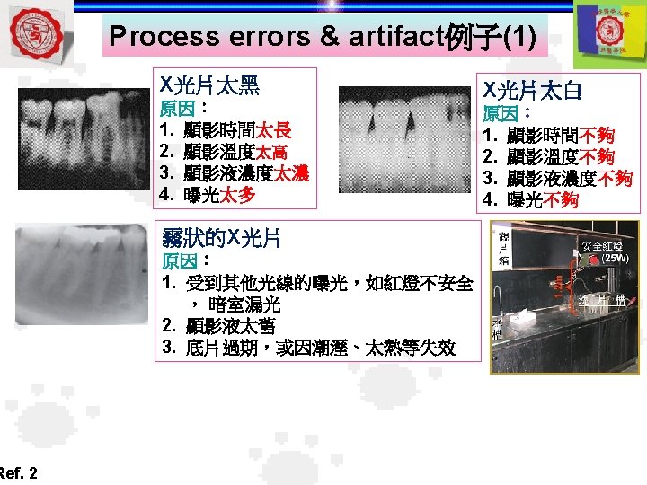
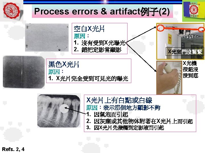
 An under developed film appears light A film with a")
 cutoff Fixer spots appear light or white Fixer cutoff appears")
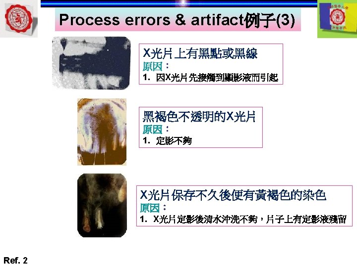
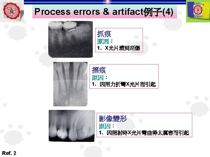
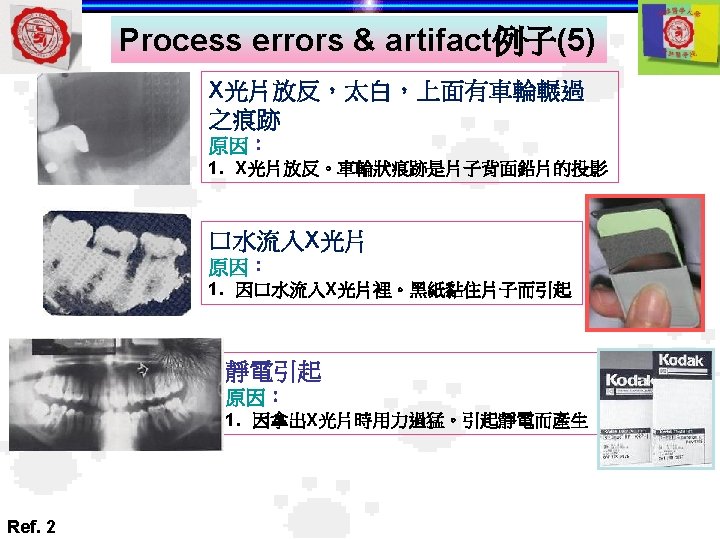
 A black fingerprint artifact appears on the film Scratches appear")
 Portion of the film exposed to light appears black Ref.")
- Slides: 40
牙科放射線學(1) Dental X-Ray Film Processing and Artifact 牙科X光片沖洗與失誤 陳玉昆教授: 高雄醫學大學 口腔病理科 07 -3121101~2755 yukkwa@kmu. edu. tw
學 習 目 標 Understand : l牙科X光片洗 片的原理與過 程 l牙科X光片洗 片的失誤原因與辨識 References 1. White & Pharoah: Oral radiology: principle & interpretation, 5 th edition, Chapter 6, p. 94 -109 2. 何復辰: 牙科放射線學 1 st edition, p. 33, 74 -79 3. Eric Whaites: Essentials of dental radiography & radiology 3 rd edition, p. 47 4. Kaohsiung Medical University, Oral Pathology Department 5. Harring JI & Jansen L: Dental radiography- principle & techniques 3 rd edition, Chapter 9, p. 101 -127 6. www. ndt-ed. org/Education. Resources/Community. College/Radiography/Tech. Calibrations. htm
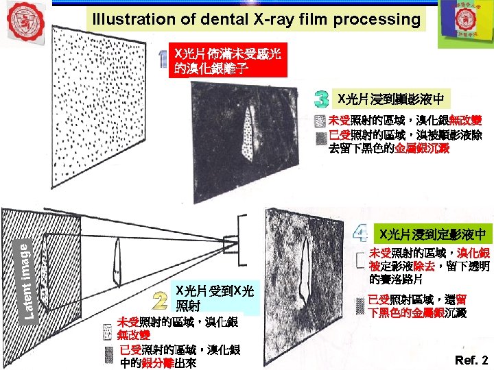
Formation of latent image 文字解說 1. Collision of X-ray photon with Br 2. Br atom, release of e 3. Attraction of e- to latent image site 4. +ve interstitial Ag ion attracted to -ve latent image site 5. Ag ion Ag atom as latent image 底片 結構 Iodide ion Bromide ion 圖片解說 底片 Latent image site - charge Silver atom (Br-) Bromide atom ion + charge Bromide atom Silver ion Interstitial silver ion + Silver atom + charge Latent image site Ref. 1 X-ray photon electron Latent image: X光片已被X光照射之區域, 但仍未產成肉眼可見之影像(visible image)
From latent image to visible image 底片 Emulsion Before X-ray exposure Emulsion After developing Ag. Br Ag Base 片 洗 After X-ray exposure Emulsion After fixing Ag. Br被洗掉 Latent image Ref. 1 Base
Microscopic image of unprocessed & processed film Processed film Unprocessed film Ref. 6
Relation of film density & exposure Changing the log of the relative exposure from 0. 75 to 1. 4, only changes the film density from 0. 20 to ~0. 30. Therefore, the film sensitivity is low. 2. 0 At film densities above 2. 0, the slope of the characteristic curve for most films is at its maximum. 0 1. 0 Film Density 3. 0 4. 0 Typical Film Characteristic Curve 0 0. 5 1. 0 1. 5 2. 0 2. 5 3. 0 Log of Relative Exposure Changing the log of relative exposure from 2. 4 to 2. 6 would change the film density from 1. 75 to 2. 75. Therefore, the film sensitivity is high in this region of the curve. The highest overall film density that can be viewed or digitized will have the highest level of contrast and contain the most useful information. Ref. 6
Factors affecting film development ange ar ch Full development Line Film density Q 1. 顯影液內何成份可解決chemical fog的問題? Chemical Temperature Development time fog 5 Development time (min) Ref. 1 650 F 680 F 700 F 720 F 6 min 5 min 760 F 3 min 4. 5 min 4 min
顯影液 成分 Phenidone(低溫作用) Hydroquinone(高溫作用) Sodium sulphite Potassium carbonate (Soften the emulsion) Benzotriazole Glutaraldehyde Fungicide Buffer Water Ref. 3 功用 Helps bring out the image Build contrast Preservative- reduces oxidation Activator- governs the activity of the developing agents Restrainer- prevents fog & the controls the activity of developing agents Softens the emulsion Prevents bacterial growth Maintains p. H (10 -11. 5) Solvent
定影液 成分 Ammonium thiosulphate (hyposulfite) Sodium sulphite Aluminum chloride Acetic acid (p. H 4 -4. 5) Water Ref. 3 功用 Removes unsensitized silver halide Preservative- prevents deterioration of the fixing agent Hardener Acidifier– maintains p. H Solvent
Factors affecting image quality Radiographic Image Quality Contrast Definition
Definition Geometric Factors n. Size of X-ray source (focal-spot size) n. X-ray source to film distance n. Specimen to detector (film) distance n. Movement of the specimen during the exposure n. Angle between source & features of interest n. Abruptness of changes in specimen thickness Film & Screen Factors n. Type of film (grain size) n. Mottling due to use of a fluorescent screen n. Wavelength of the primary radiation n. Development time and other film processing factors Radiographic definition: Abruptness of change in going from one area of a given radiographic density to another Ref. 6
Size of source (focal-spot size) Source Focal Spot Subject Detector Penumbra Ref. 6 Detector Penumbra
Angle between X-ray source & features of interest X-ray source Well defined feature Ref. 6 X-ray source Distorted and less defined feature
Abruptness of changes in specimen thickness Stepwedge High Definition Radiograph Low Definition Radiograph Ref. 6
Contrast Subject Factors n. Absorption differences in the subject n. Wavelength of the primary radiation n. Secondary radiation from scatter Film & Screen Factors n. Type of film (grain size) n. Chemistry of film processing chemicals n. Concentrations of film processing chemicals n. Developing time n. Amount of film agitation n. Overall film density n. Use of screens Radiographic contrast: The degree of density difference between two areas on a radiograph Ref. 6
Absorption differences in the subject Stepwedge High Contrast Radiograph Low Contrast Radiograph Ref. 6
Wavelength of the primary radiation Low k. V 4 to 1 Ref. 6 High k. V 2 to 1
Various types of image quality Since radiographic contrast & definition are not dependent upon the same set of factors, it is possible to produce radiographs with the following qualities: u. Low contrast and poor definition u. High contrast and poor definition u. Low contrast and good definition u. High contrast and good definition Ref. 6
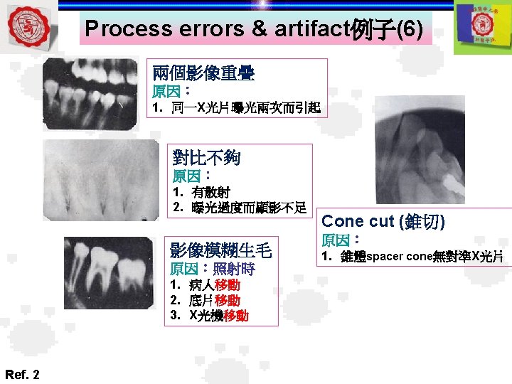
Process errors & artifact例子(7) An under developed film appears light A film with a damaged emulsion appears crack Ref. 5 An over developed film appears dark Developer spots appear dark or black
Process errors & artifact例子(8) cutoff Fixer spots appear light or white Fixer cutoff appears as a straight white border on a film A number of processing errors result in a yellow-brown film Ref. 5 Developer cutoff appears as a straight black border on a film
Process errors & artifact例子(9) A black fingerprint artifact appears on the film Scratches appear as thin white lines Ref. 5 Static electricity appears as black branching lines
Process errors & artifact例子(10) Portion of the film exposed to light appears black Ref. 5 A fogged film appears gray & lacks detail & contrast