1 Billion Transistors K 1 000 100 000

Брой транзистори 1 Billion Transistors K 1, 000 100, 000 1, 000 i 386 80286 100 10 i 486 Pentium® III Pentium® Pro Pentium® 8086 Source: Intel 1 1975 1980 1985 1990 1995 2000 2005 2010 Thermal management Courtesy, Intel 5
 1000 2 X growth in 1. 96")
Законът на Мур при микропроцесорите Transistors (MT) 1000 2 X growth in 1. 96 years! 100 10 486 1 P 6 Pentium® proc 386 286 0. 1 8086 8080 8008 4004 8085 Transistors on Lead Microprocessors double every 2 years 0. 01 0. 001 1970 Thermal management 1980 1990 Year Courtesy, Intel 2000 2010 6
 10000 Doubles every 2 years 1000 10 8085 1 0. 1")
Честотата Frequency (Mhz) 10000 Doubles every 2 years 1000 10 8085 1 0. 1 1970 8086 286 386 486 P 6 Pentium ® proc 8080 8008 4004 1980 1990 Year 2000 2010 Lead Microprocessors frequency doubles every 2 years Thermal management Courtesy, Intel 7
 100 P 6 Pentium ® proc 10 8086 286 1")
Отделяна мощност Power (Watts) 100 P 6 Pentium ® proc 10 8086 286 1 8008 4004 486 386 8085 8080 0. 1 1974 1978 1985 1992 2000 Year Lead Microprocessors power continues to increase Thermal management Courtesy, Intel 8
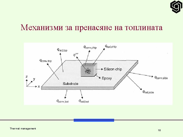
 10000 100 Rocket Nozzle Nuclear Reactor 8086")
Плътност на мощността Power Density (W/cm 2) 10000 100 Rocket Nozzle Nuclear Reactor 8086 10 4004 Hot Plate P 6 8008 8085 Pentium® proc 386 286 486 8080 1 1970 1980 1990 2000 2010 Year Power density too high to keep junctions at low temp Thermal management Courtesy, Intel 9
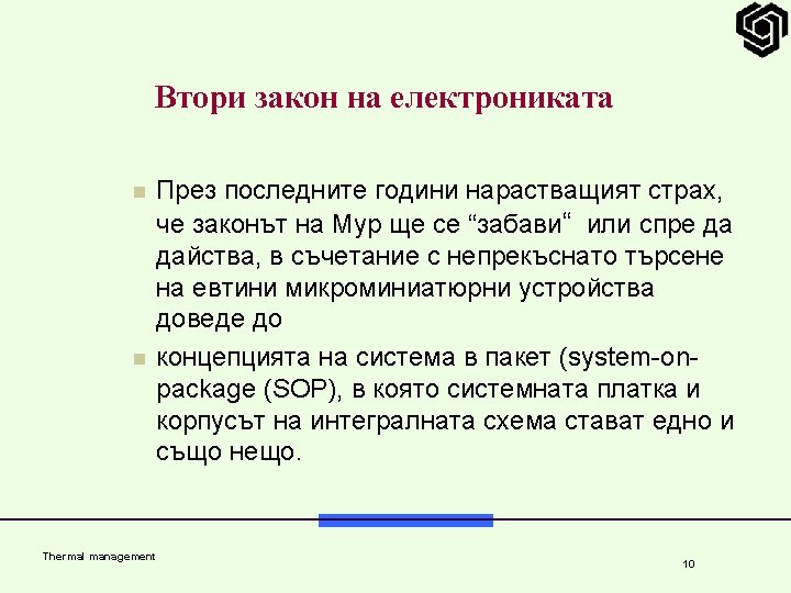

Second law of electronics n The SOP technology integrates a number of leading-edge technology waves that include n digital, n RF, n micro-electromechanical systems (MEMS), n sensors, and n optoelectronics n in a highly miniaturized system package. n The focus of SOP is thus on miniaturization of system components, including not only actives but also passives, power sources, I/Os, thermal structures, and system I/Os. Thermal management 11

Why Thermal Management of Microsystems? n Single microelectronic chip may include as many as 1 milliard transistors. n Many tens of such components may be used in a single system. n The minimization or elimination of thermally-induced failures requires the reduction of the temperature rise above the ambient and minimization of temperature variations within the packaging structure(s). Thermal management 12

Thermal management 13

Тенденции при плътността на мощността n Power dissipation n Hot spots n Cost of cooling n Low cost cooling n n n Air flow fans Heat sinks Expensive cooling solutions n n Thermal management Liquid cooling Refrigeration 14

Надеждността и функционирането – зависими от топлината n Operating temperatures outside a range can cause deteriorated performance of active semiconductors- the leakage current may increase in DRAM, n clock frequency may reduce, and n wavelength drift and power drop may occur in optoelectronic modules. n Thermal management 15

Надеждността и функционирането – зависими от топлината n The mismatch in the coefficient of thermal expansion (CTE) between ICs and organic substrates 2. 8 ppm/°C for Si, n ~6 ppm/°C for Ga. As, n -25 ppm/°C for eutectic Sn 63 Pb 37 solder, and n 14 to 20 ppm/°C for organic epoxy fiberglass FR 4 n n generates thermal stress at the solder joints. Thermal management 16

Надеждността и функционирането – зависими от топлината n The International Technology Roadmap for Semiconductors (ITRS) provides a projected value of allowable junction and operating temperatures in various microsystems. n The junction temperature for n n n single chip-packaged devices can't be allowed to rise above 125°C in low-cost, handheld, and memory devices; above 175°C in devices working in harsh environment; and above 100°C in high-performance and cost-effective devices. Thermal management 17
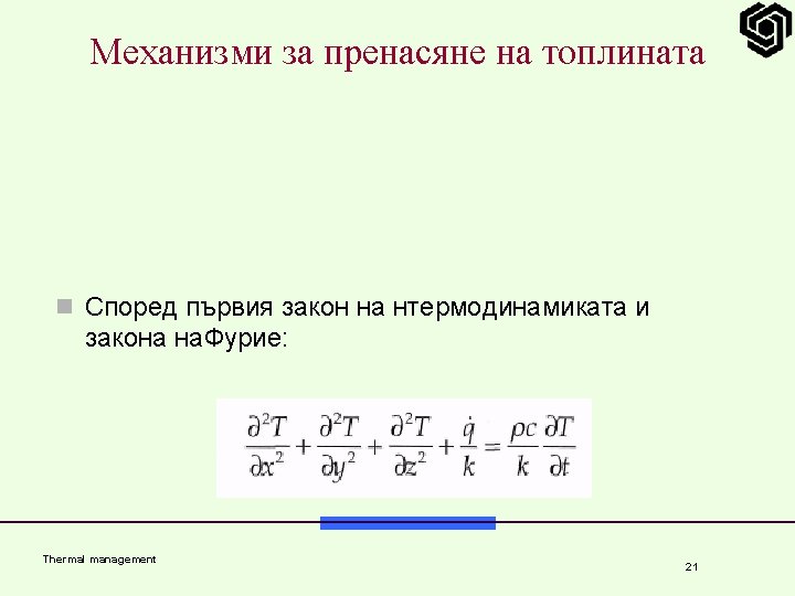

Fundamental Heat Transfer Modes n By applying the first law of thermodynamics and Fourier's law to an incremental control volume and in the cartesian coordinate system it is given as: Thermal management 22


Thermal management 25

Thermal management 26

Classical heat pipe Condenser Adiabatic Evaporator Wick Liquid-vapour two-phase-loop, with evaporation at the one end (heat source) and condensation at the other end (heat sink) Thermal management Garner, Electronics Cooling, 02, 1996 27

Loop Heat Pipe In the LHP the evaporator and condenser components are separated. LHPs can transport a large amount of heat over long distances with minimal temperature drop & excellent performance against gravity. Thermal management 28

Loop heat pipe Liquid supply to evaporator by capillary action Axial grove Compensation chamber Evaporation Vapor line Adiabatic Liquid line Adiabatic Condenser Radiation/ convection Thermal management Liquid line Liquid Condenser Radiation/ convection 29

Pulsating heat pipe Thermal management Kahandekar et al. , Electronics Cooling, 05, 2003 30

Pulsating heat pipe PHP has no complicated wick structure, is easy to produce, and is capable of higher power transportation. Gravity has little influence on a PHP. Thermal management Kahandekar et al. , Electronics Cooling, 05, 2003 31

Packaging 3 D Introduction Projet « Microcooling » Thalès Avionics Thèse de N. Popova • Capot avec broches Intégrer un caloduc (dispositif de changement de raccordement de phase d’un fluide) • Dissiper 34 W • Épaisseur max/niveau composants = 1, 8 mm Interconnections électriques Substrat double face Connections thermiques Composants source froide Thermal management Refroidissement actif Boîtier 33 4/45

Stacked 3 D module Clamping I/O PCB system 3 D packaging Thermal drains 3 single sided substrates with heat pipe Initial design Substrates with only 0. 9 mm thickness Interconnections Substrate 1 double sided substrate with heat pipe Casing Improved design Project requirements § maximal thickness of the double sided substrate 1. 8 mm § heat power dissipation should be at least 50 W Substrate with 1. 8 mm thickness § to work against gravity Thermal management 34

HEAT PIPE OPERATION Heat sources Condenser Heat pipe Condenser Heat sources Heat enters the heat pipe and evaporates the liquid in the wick n The liquid evaporates (evaporator section) with an important heat absorption (latent heat) n The vapor flows to the cold part (condenser) of the heat pipe n There the vapor condenses releasing its latent heat n And the liquid returns to the evaporator by capillary effects Thermal management Cold source Vapor condenses heat exits the HP 35

Introduction Flat Micro Heat Pipe Operation Caloduc intégré dans le substrat multi puces sources chaudes source chaude espace vapeur liquide source froide réseau capillaire saturé de liquide enveloppe source froide FMHPs are typically used for cooling PCBs or for heat levelling to produce an isothermal plane. They could be embedded directly onto the silicon substrate of an integrated circuit. Thermal management 36 6/45

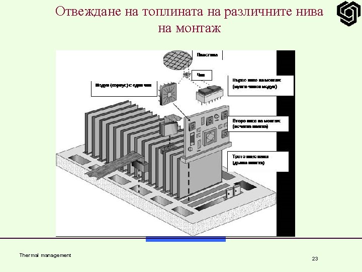
Packaging Level Passive Cooling Techniques Active Cooling Techniques IC Package High-conductivity adhesive Air jet impingement Level 1 Greases Dielectric liquid Phase change materials High conductivity molding compound Heat spreader Heat sinks Dielectric liquid immersion Heat pipes PWB Thermal management Thick power and ground planes Fans 37

Packagi Passive Active ng Cooling Level Technique es s Level 2 Insulated metal substrates Dielectric liquids Heat pipes Cold plates Natural convection Module and rack Natural Air handling convection Level 3 +4 Heat pipes Thermal management Cold plates 38

Thermal Characterization n The objective of thermal characterization is to determine the temperature fields within the system, with the appropriate resolution spatially and temporally. n As part of the design process of a microsystem it is necessary to characterize thermal fields through modelling and measurements. Thermal management 40

Numerical Methods for Thermal Characterization n Analytical or closed-form solutions approach n Suitable for a class of idealized situations involving the chip, package, or module. n In this approach, the heat input is usually prescribed as a uniform heat flux or as a uniform volumetric heat generation rate such that exact solutions of linear sets of governing equations can be obtained. Thermal management 41

Numerical Methods for Thermal Characterization n Resistor network approach n 1 D and 2 D heat conduction resistances in rectangular and radial geometries are utilized to simulate thermal characteristics of the package. n This method is usually used at the package, module, and system levels. Thermal management 42

Numerical Methods for Thermal Characterization n Numerical solutions of the discretized governing differential equations n n n This method belongs to the broad subject of computational fluid dynamics (CFD). It can be used for simulations at the package or PWB level to solve the heat conduction equation in two or three dimensions or for simulations of coupled fluid flow and heat transfer in the entire electronic systems. Since CFD simulations are capable of producing a detailed temperature distribution, they can also be used for evaluating thermomechanical stresses, especially in locations containing packaging materials with unequal coefficients of thermal expansion. Thermal management 43

Thermal management 44
- Slides: 44