1 6 Frequency response of amplifiers Measuring the


 a lowpass")
 Magnitude and (b) phase response")
 Magnitude and (b) phase response of STC")


- Slides: 36
1. 6 Frequency response of amplifiers Measuring the amplifier frequency response Figure 1. 20 Measuring the frequency response of a linear amplifier: At the test frequency ω , the amplifier gain is characterized by its magnitude (Vo /Vi) and phase . Sedra/Smith Copyright © 2011 by Oxford University Press, Inc.
Amplifier Bandwidth – The band of frequencies over which the gain of the amplifier is almost constant, to within a certain number of decibels (usually 3 d. B)
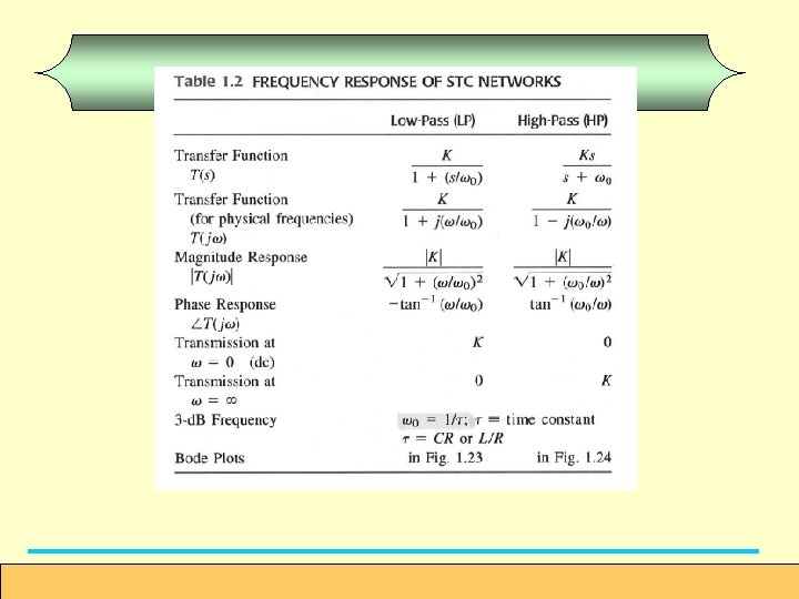
Single Time Constant Figure 1. 22 Two examples of STC networks: (a) a lowpass network and (b) a high-pass network. Microelectronic Circuits, International Sixth Edition
Bode Plots Low Pass Filter Figure 1. 23 (a) Magnitude and (b) phase response of STC networks of the low-pass type. Microelectronic Circuits, International Sixth Edition
High Pass Filter Figure 1. 24 (a) Magnitude and (b) phase response of STC networks of the high-pass type. Microelectronic Circuits, International Sixth Edition
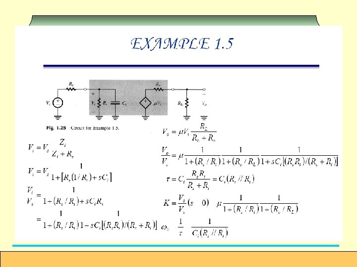
Figure 1. 25 Circuit for Example 1. 5. Microelectronic Circuits, International Sixth Edition
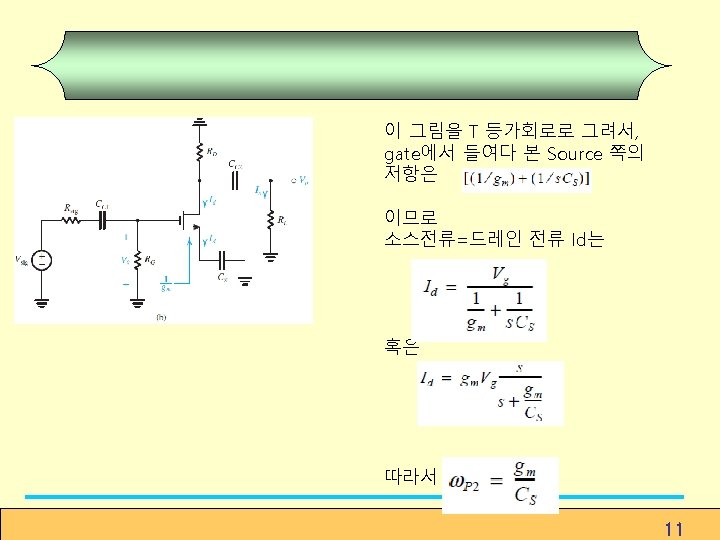
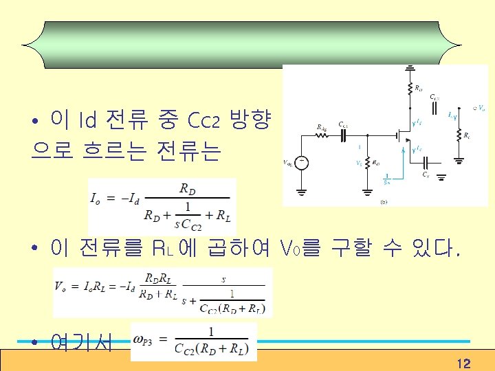
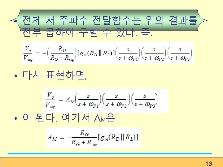
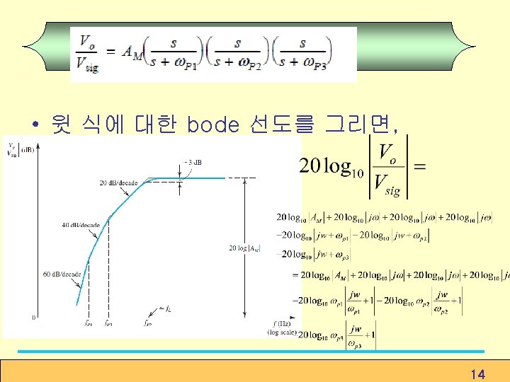
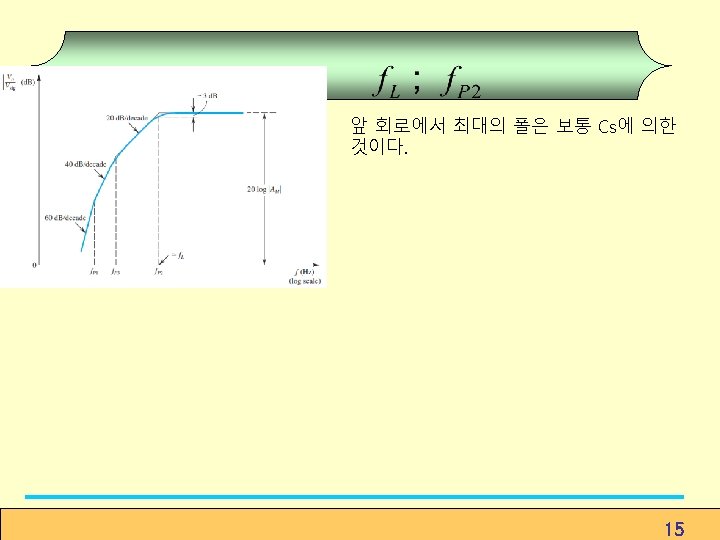
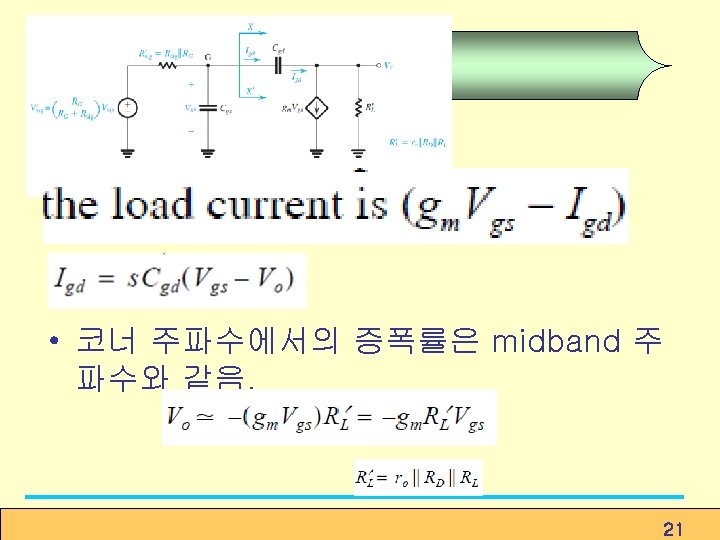
Low Frequency Response of the Common Source Amplifiers • 9
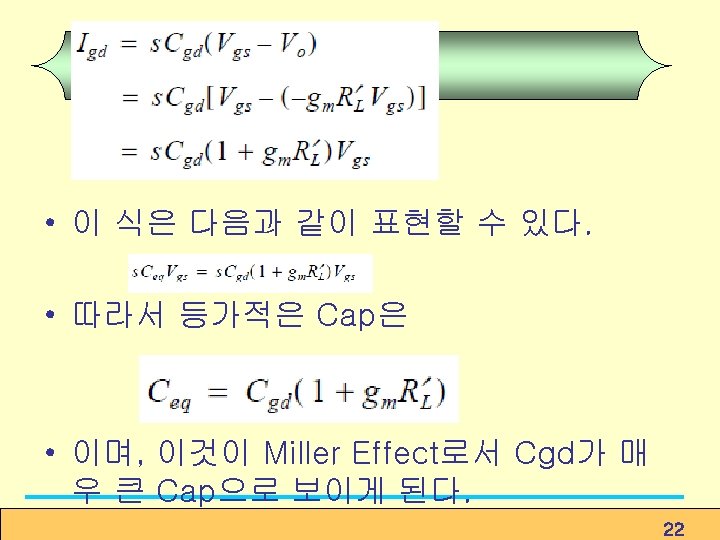
High Pass Filter의 폼. Corner frequency w 0는 10
• Internal Capacitive Effects and the High Frequency Model of the MOSFET 16
17
18
High Frequency Response of the CS amplifiers 19
20
• Miller’s Theorem 25
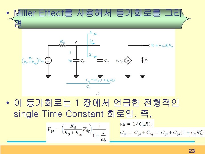
Useful Tools for the Analysis of the High. Frequency Response of Amplifiers Using Miller’s Theorem
8. 6 High-Frequency Response of the Common. Gate and Cascode Amplifier High-Frequency Response of the Common-Gate Amplifier Common Gate Amplifier with internal capacitance Equivalent Circuit 32
33
High-Frequency Response of MOS Cascode Amplifier Figure 8. 38 The cascode circuit with the various transistor capacitances indicated. 34
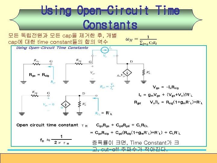
일 경우. Determine the 3 -d. B frequency f. H ① employ the open-circuit timeconstant method. ② effective time constant ③ 3 -d. B frequency Cut-off 주파수가 크다. (8. 138) ④ unity-gain frequency Figure 8. 38 The cascode circuit with the various transistor capacitances indicated. (8. 139) 35
8. 10. 2 Frequency Response of the Source Follower Find zero frequency ① ② ③ Since ④ Find pole frequency ① Rgd seen by Cgd, (8. 174) ② (8. 175) ③ ④ (8. 176) Figure 8. 51 Analysis of the high-frequency response of the source follower: (a) Equivalent circuit; (b) simplified equivalent circuit; and (c) determining the resistance Rgs seen by Cgs. 36